Specification
| Model |
TR D3-15-23000-220Y/127 |
TR D3-30-23000-220Y/127 |
TR D3-45-23000-220Y/127 |
TR D3-75-23000-220Y/127 |
TR D3-112.5-23000-220Y/127 |
TR D3-150-23000-220Y/127 |
TR D3-225-23000-220Y/127 |
TR D3-300-23000-220Y/127 |
TR D3-500-23000-220Y/127 |
| KVA Rating |
15 |
30 |
45 |
75 |
112.5 |
150 |
225 |
300 |
500 |
| No-Load Loss (W) |
90 |
126 |
170 |
240 |
315 |
360 |
520 |
660 |
1050 |
| Full Load Loss at 85℃ (W) |
206 |
373 |
533 |
811 |
1144 |
1447 |
2144 |
2680 |
3972 |
| Total Losses (W) |
222 |
365 |
511 |
759 |
1047 |
1286 |
1892 |
2375 |
3592 |
| 80% Load Efficiency (%) |
98.18 |
98.5 |
98.6 |
98.75 |
98.85 |
98.94 |
98.96 |
99.02 |
99.11 |
| Impedance (%) |
2.0~4.0 |
2.0~4.0 |
2.0~4.0 |
2.0~4.0 |
2.0~4.0 |
2.0~4.0 |
2.0~4.0 |
2.0~4.0 |
2.0~4.0 |
| Oil Weight (L) |
89 |
98 |
114 |
137 |
168 |
205 |
256 |
295 |
315 |
| Total Weight (KG) |
250 |
285 |
337 |
436 |
505 |
625 |
745 |
910 |
1050 |
| Dimension (mm) A |
950 |
980 |
1120 |
1180 |
1220 |
1260 |
1300 |
1350 |
1380 |
| Dimension (mm) B |
570 |
600 |
620 |
650 |
680 |
1050 |
1080 |
1220 |
1260 |
| D (mm) |
520 |
550 |
580 |
580 |
580 |
620 |
620 |
660 |
660 |
| H (mm) |
950 |
950 |
1000 |
1050 |
1070 |
1150 |
1180 |
1230 |
1230 |
| Winding Material |
AL-AL |
AL-AL |
AL-AL |
AL-AL |
AL-CU |
AL-CU |
AL-CU |
AL-CU |
AL-CU |
If you are interested in our transformers and related transformer accessories, please get more information and professional solutions through this website or directly through info@wishpower.net
What is the 25 kV 3–phase Pole–transformer?
25 kV 3-phase pole transformer is an electrical transformer, various types of which are used in distribution systems. Its main application is to transform voltages such as high voltage to a voltage level that is safe for the end consumers to use. It’s often used in utility poles organizing the electric power distribution both in rural and urban areas. The transformer uses a nominal voltage of 25 kV at the primary winding, which is normally provided by the high-voltage transmission system. On the secondary side, it transforms this voltage to a lower, more convenient for consumers, a voltage level which is typically 120/240V or 480V according to the standard voltage on the local electricity grid. What it means is that it can support three-phase power, which is crucial in the distribution of electric power over large distances and for large industrial, commercial, and residential consumers. Thanks to the load balance provided by this type of transformer, there is a more stable and efficient method of power supply. Since the transformer is pole mounted means that it can directly be fixed on the electrical poles and hence will suit areas with limited land space or where the underground solution is not practical.
Structure and other requirements of the 3–phase Pole–transformer
- Layout requirements
1.1 The layout of the transformer body, bushing, oil storage cabinet, and radiator shall meet the requirements of the buyer.
1.2 Transformer components shall be selected from qualified products that have passed the national transformer component rectification.
1.3 Coil manufacturing shall meet the requirements of the two-part improvement measures. High-voltage leads and welding heads shall be shielded, and lead welding shall be silver-copper welding.
1.4 Electromagnetic wire shall use oxygen-free copper wire.
1.5 The core shall be made of high-performance and high-quality cold-rolled silicon steel sheets, and the core and larger metal structural parts shall be reliably grounded through the oil tank.
1.6 The transformer casing shall be treated with rust and corrosion prevention. The casing and paint shall ensure quality and meet the 3-year maintenance-free requirement. If the transformer paint is damaged during transportation and installation, the manufacturer shall be responsible for repainting on-site.
1.7 Ensure that the transformer is leak-free.
2 Core and winding
2.1 The core should be made of high-quality, low-loss grain-oriented cold-rolled silicon steel sheets, and should be stacked and fastened by advanced methods to prevent the transformer core from loosening due to vibration during transportation and operation.
2.2 All windings should use copper wires or copper foils, and semi-hard copper wires are preferred.
2.3 The coil winding, set-up, and pressing should have strict fastening process measures, and the lead wires should have sufficient support to make the body form a tight hole with sufficient short-circuit resistance.
3 Oil conservator
3.1 If the transformer is equipped with an oil conservator, its structure should be easy to clean inside. The volume of the oil conservator should ensure that the oil does not overflow under the highest ambient temperature and allowable load conditions. At the lowest ambient temperature and when the transformer is not put into operation, the oil level gauge should have visible oil.
3.2 The oil in the oil conservator should be isolated from the atmosphere, and the amount of oil in it can be adjusted by the expansion or contraction of the capsule.
3.3 The oil conservator should have oil filling, oil draining, and sewage discharge devices. The oil storage cabinet shall be equipped with a desiccant with an oil seal.
3.4 An oil level gauge shall be installed at one end of the oil storage cabinet.
4 Oil tank
4.1 Water shall not accumulate on the top of the transformer oil tank, and there shall be no dead corners inside the oil tank.
4.2 An oil sample valve shall be installed on the lower wall of the oil tank, and a sufficiently large oil drain valve shall be provided. The bottom of the oil tank of transformers of 400kVA and above shall be equipped with an oil drain device.
4.3 The sealing surfaces of all flanges shall be flat, and the gaskets shall have appropriate limits to prevent the gaskets from being over-pressurized and cracked and aging to cause leakage.
5 Cooling device
5.1 The type and manufacturer shall generally be provided by the bidder.
5.2 The load capacity of the transformer shall comply with the requirements of GB/T 1094.7, and the seller shall provide a calculation report of the short-term emergency overload capacity.
5.3 The cooling system of the transformer for dry-type stations can be started manually and automatically, and the starting mode is achieved through the conversion switch. The automatic mode can automatically start or cut off the cooling system according to the winding temperature and transformer load, and reasonably select the return value and start value to avoid frequent fan operation.
When the cooler system fails during operation, it should be able to send an accident signal and provide an upload signal interface. The cooling system control box should be supplied with the transformer as a complete set. The control box should be outdoors and equipped with a digital display intelligent temperature controller, which can output high-temperature alarm and ultra-high temperature tripping signals, as well as 4mA~20mA standard microcomputer signals of temperature. The transformer should be equipped with a low-voltage side neutral point current transformer.
6 Bushing
6.1 The bushing should not leak.
6.2 The test and other performance requirements of the bushing should comply with GB/T 4109.
7 Tap changer
7.1 The on-load tap changer should be S-type.
7.2 The switching device of the on-load tap changer should be installed in an oil chamber that is separated from the main oil tank of the transformer and does not leak. The switching switch core can be lifted out for maintenance separately.
7.3 The oil chamber of the on-load tap changer shall have a separate oil storage cabinet, desiccant, pressure relief device protective relay, etc.
7.4 The drive motor and accessories of the on-load tap changer shall be installed in a control box with good weather resistance.
7.5 The on-load tap changer shall be able to be operated remotely or manually next to the transformer. It shall be equipped with an action recorder for the cumulative number of switching times and a tap position indicator. The control circuit shall have a computer interface.
7.6 The oil chamber of the on-load tap changer shall be able to withstand an oil pressure test of 0.05MPa pressure and last for 24 hours without leakage.
7.7 The on-load tap changer shall be easily maintained and repaired without changing the oil tank.
7.8 The tap changer shall comply with the provisions of GB/T 10230.
8 Insulating oil
The insulating oil used for the transformer shall be new oil that complies with the provisions of GB 2536.
9 Temperature measuring device
The transformer shall be equipped with an oil temperature measuring device. In addition to being observable on the transformer body, the above temperature variables should also be able to send out the signal.
10 Painting and rust prevention
10.1 The outer surfaces of the transformer oil tank, oil storage cabinet, cooling device, and connecting pipe should be painted, and the color should be according to the buyer’s requirements.
10.2 The inner surface of the transformer oil tank, the upper and lower clamps of the core, etc. should be painted with light-colored paint and have good compatibility with the transformer oil. The paint is determined by the seller. All surfaces that need to be painted should be thoroughly treated before painting (such as sandblasting or shot peening).
10.3 A layer of metal primer should be applied within 8 hours after sandblasting (shot peening) and before rust occurs. The primer should have good anti-corrosion, moisture-proof, and adhesion properties, and the paint layer thickness should not be less than 0.04mm. The surface topcoat is compatible with the primer and has good durability.
10.4 All external surfaces shall be painted with at least one primer and two topcoats, with a topcoat thickness of not less than 0.085mm. The surface topcoat shall be sufficiently elastic to withstand temperature changes, resist peeling, and not fade or powder.
10.5 When the transformer leaves the factory, the external surface shall be freshly painted, and an appropriate amount of original paint shall be provided for touch-up or overall painting at the installation site.
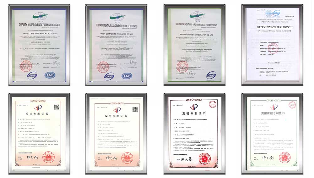
Certificate
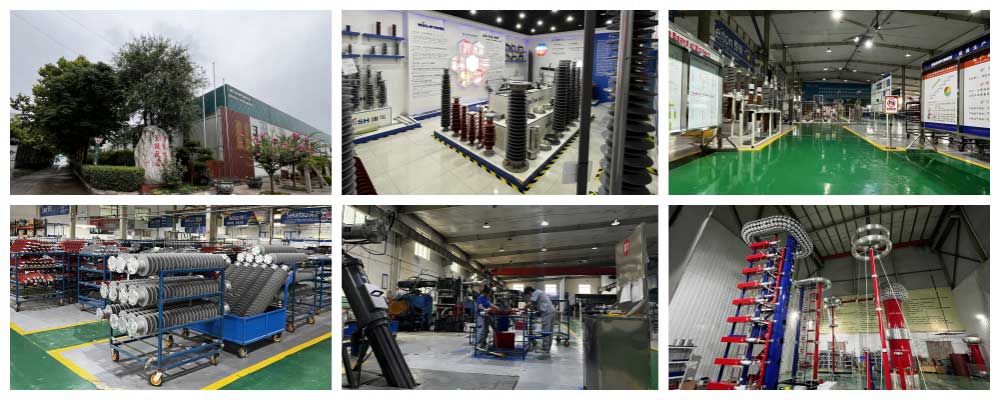
Factory
Hot Tags: 25 kV 3-phase Pole-transformer, transformer, made in Thailand available, manufacturers, ISO factory, wholesale, KEMA, high quantity, best, price, low to high voltage


